- 您现在的位置:买卖IC网 > Sheet目录1992 > CY28323OXC (Silicon Laboratories Inc)IC CLOCK BROOKDALE GPENT4 48SSOP
CY28323PVC
..Document #: 38-07004 Rev. *B Page Page 11 of 21 of 21
Bit 6
--
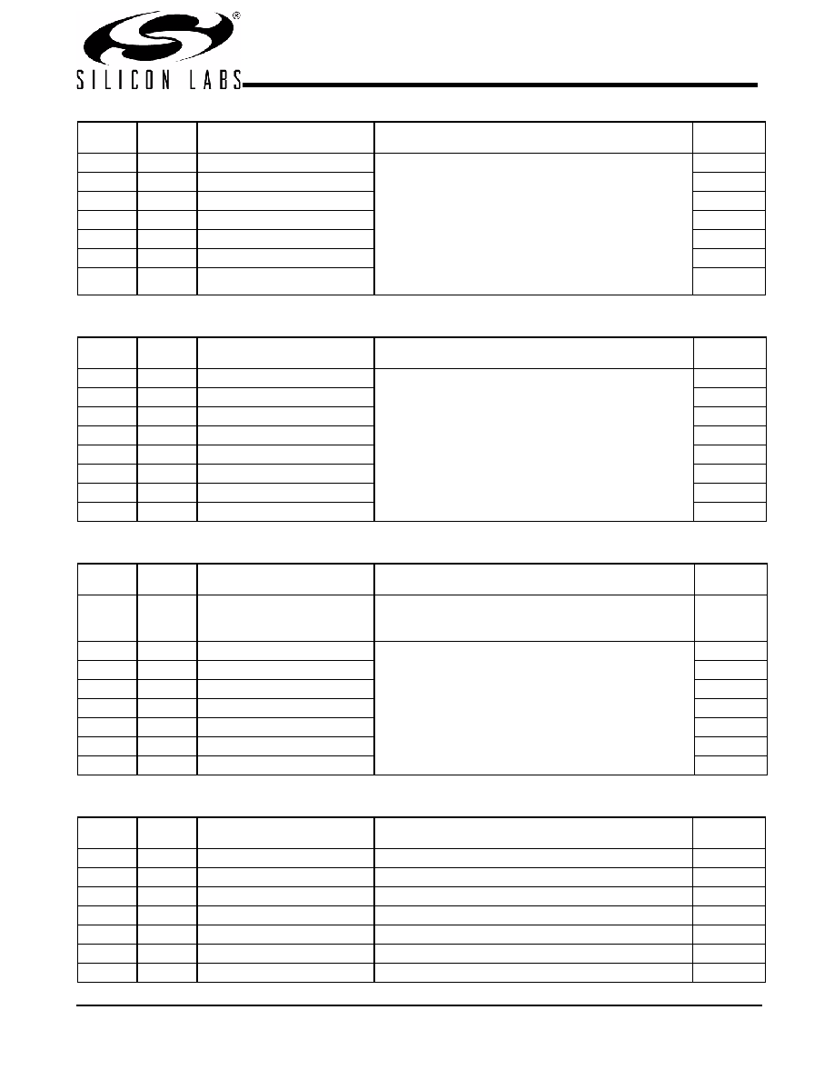
ROCV_FREQ_M6
If ROCV_FREQ_SEL is set, the values programmed in
ROCV_FREQ_N[7:0] and ROCV_FREQ_M[6:0] will be
use to determine the recovery CPU output frequency.when
a Watchdog timer time-out occurs.
The setting of FS_Override bit determines the frequency
ratio for CPU and other output clocks. When the
FS_Override bit is cleared, the same frequency ratio stated
in the Latched FS[4:0] register will be used. When it is set,
the frequency ratio stated in the SEL[4:0] register will be
used.
0
Bit 5
--
ROCV_FREQ_M5
0
Bit 4
--
ROCV_FREQ_M4
0
Bit 3
--
ROCV_FREQ_M3
0
Bit 2
--
ROCV_FREQ_M2
0
Bit 1
--
ROCV_FREQ_M1
0
Bit 0
--
ROCV_FREQ_M0
0
Data Byte 12 (continued)
Bit
Pin#
Name
Pin Description
Power On
Default
Data Byte 13
Bit
Pin#
Name
Pin Description
Power On
Default
Bit 7
--
CPU_FSEL_N7
If Prog_Freq_EN is set, the values programmed in
CPU_FSEL_N[7:0] and CPU_FSEL_M[6:0] will be used to
determine the CPU output frequency. The new frequency
will start to load whenever CPU_FSELM[6:0] is updated.
The setting of the FS_Override bit determines the
frequency ratio for CPU and other output clocks. When it is
cleared, the same frequency ratio stated in the Latched
FS[4:0] register will be used. When it is set, the frequency
ratio stated in the SEL[4:0] register will be used.
0
Bit 6
--
CPU_FSEL_N6
0
Bit 5
--
CPU_FSEL_N5
0
Bit 4
--
CPU_FSEL_N4
0
Bit 3
--
CPU_FSEL_N3
0
Bit 2
--
CPU_FSEL_N2
0
Bit 1
--
CPU_FSEL_N1
0
Bit 0
--
CPU_FSEL_N0
0
Data Byte 14
Bit
Pin#
Name
Pin Description
Power On
Default
Bit 7
--
Pro_Freq_EN
Programmable output frequencies enabled
0 = disabled
1 = enabled
0
Bit 6
--
CPU_FSEL_M6
If Prog_Freq_EN is set, the values programmed in
CPU_FSEL_N[7:0] and CPU_FSEL_M[6:0] will be used to
determine the CPU output frequency. The new frequency
will start to load whenever CPU_FSELM[6:0] is updated.
The setting of the FS_Override bit determines the
frequency ratio for CPU and other output clocks. When it is
cleared, the same frequency ratio stated in the Latched
FS[4:0] register will be used. When it is set, the frequency
ratio stated in the SEL[4:0] register will be used.
0
Bit 5
--
CPU_FSEL_M5
0
Bit 4
--
CPU_FSEL_M4
0
Bit 3
--
CPU_FSEL_M3
0
Bit 2
--
CPU_FSEL_M2
0
Bit 1
--
CPU_FSEL_M1
0
Bit 0
--
CPU_FSEL_M0
0
Data Byte 15
Bit
Pin#
Name
Pin Description
Power On
Default
Bit 7
--
Reserved
0
Bit 6
--
Reserved
0
Bit 5
--
Reserved
0
Bit 4
--
Reserved
0
Bit 3
--
Reserved
0
Bit 2
--
Reserved
0
Bit 1
--
Vendor Test Mode
Reserved. Write with “1”
1
发布紧急采购,3分钟左右您将得到回复。
相关PDF资料
CY28354OXC-400
IC BUFF 273MHZ 4DDR DIMM 48SSOP
CY28378OXC
IC CLOCK CK408/TITAN 845 48SSOP
CY284108ZXC
IC CLOCK SERV CK410B 56TSSOP
CY28410OXC-2
IC CLOCK CK410 GRANTSDALE 56SSOP
CY28410OXC
IC CLOCK CK410 GRANTSDALE 56SSOP
CY28411ZXC
IC CLOCK CK410M ALVISO 56TSSOP
CY28442ZXC-2
IC CLOCK ALVISO PENTM 56TSSOP
CY28445LFXC-5
IC CLOCK CALISTOGA CK410M 68QFN
相关代理商/技术参数
CY28323OXCT
功能描述:时钟发生器及支持产品 Brookdale RoHS:否 制造商:Silicon Labs 类型:Clock Generators 最大输入频率:14.318 MHz 最大输出频率:166 MHz 输出端数量:16 占空比 - 最大:55 % 工作电源电压:3.3 V 工作电源电流:1 mA 最大工作温度:+ 85 C 安装风格:SMD/SMT 封装 / 箱体:QFN-56
CY28323PVC
制造商:Rochester Electronics LLC 功能描述:- Bulk
CY28324
制造商:CYPRESS 制造商全称:Cypress Semiconductor 功能描述:FTG for Intel Pentium 4 CPU and Chipsets
CY28324_02
制造商:CYPRESS 制造商全称:Cypress Semiconductor 功能描述:FTG for Intel㈢ Pentium㈢ 4 CPU and Chipsets
CY28324PVC
制造商:Cypress Semiconductor 功能描述:PLL Frequency Generator Dual 48-Pin SSOP 制造商:Rochester Electronics LLC 功能描述:- Bulk
CY28324PVCT
制造商:Rochester Electronics LLC 功能描述:- Tape and Reel
CY28325-2
制造商:CYPRESS 制造商全称:Cypress Semiconductor 功能描述:FTG for VIA Pentium 4 Chipsets
CY28325-3
制造商:SPECTRALINEAR 制造商全称:SPECTRALINEAR 功能描述:FTG for VIA⑩ Pentium 4⑩ Chipsets